There are 3 other sections.
1) Skip the theory, and let the computer do all the work.
2) Go to the Gain VS Height above ground. graph. 3) Go to the Take-off Angle VS Height area.
The theory starts here.
There are lots of yagi design programs on the web, but most of them do not tell you what particular strength the designer was aiming for. As you probably know by now, all YAGI antennas are a COMPROMISE between various desirable qualities. You can not have them all. This design is for the greatest FORWARD GAIN, and not any of the other possible qualities that a YAGI antenna can have.
EZNEC* claims this antenna has around 11.9 dBi gain, but that seems far too high to me. I expect about 7 dBi or 8 dBi maximum.The theory works for ANY frequency you choose, from below 160 meters to way above 440 MHz.
( The 80 meter version was used for Field Day 2006 in Olympia, WA by the Olympia Amateur Radio Society)
If it really has 11.9 dBi gain and you put 100 watts into the antenna, it will behave like 1548 Watts in the forward direction.
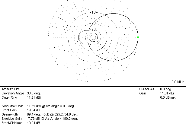
10 Watts in results in 154.8 Watts out in the forward direction. This is a fantastic antenna, but that just seems like far too much to believe. I suspect that 8 dBi is probably more correct, but even 8 dBi will mean that 100 Watts in will behave like 630 Watts in the direction the yagi is aimed.A couple of charts from EZNEC will help show what the calculations claim for this antenna. This Azmuth Plot graph shows the gain, and also says that the beam width is 138 degrees between the 3 dB gain markers. The FRONT to BACK ratio is 19 dB, which is not fantastic, but that is not what I was after.
Go to the Azmuth Plot to see an EZNEC graph of an 80 meter antenna 100 feet in the air.
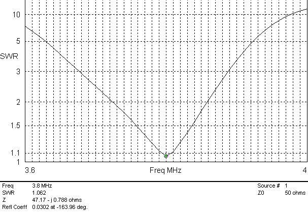
The next graph shows the SWR plot for this antenna. I calculate that the bandwidth that is below the SWR = 3:1 is 4.7% of the center frequency. That means that the limits of this antenna are from 3.62 mHz to 3.98 mHz, which covers most of the SSB portion of this band. If you want to use this antenna outside of the range shown here, you will need to use an antenna tuner. Go to the EZNEC SWR graph to see this.To keep things very simple, I will ignore most of the things that a Ph.D in Electrical Engineering would think about. This is a simple, easy design, and it is true that the Ph.D could get a bit more gain from her 3 element Yagi.
First, it does NOT matter what you use for the boom. It can be a conductor (metal) or insulator (wood or plastic), or you can choose to use NO BOOM at all. You could make a 'wire yagi' instead.
Second, the spacing between the driven element and the refelector will be the SAME as the spacing between the driven element and the director element. Both of these distances will be 0.2 wavelengths long. We will do the calculatons soon. So far, this is a really simple antenna.
The director will be 5% shorter than the driven element, and the reflector will be 5% longer than the driven element. Keep it simple.
The design starts here. What you need to know.
You will need to know 6 things, and you already know many of them.
1) How to convert feet into inches. (Multiply by 12.)Note:
2) Length of the driven element = 468 / Freq (in MHz)
The driven element will need to be cut in half and connected to the feed line where it has been cut. The center wire of the feed line goes to the end of one of the halves of the driven element, and the outside of the coax feedline goes to the end of the other half of the driven element. Use an insulator for holding the ends close together.
3) The director will be 5% shorter than the driven element. This is not cut in half.4) The reflector will be 5% longer than the driven element. This is not cut in half.
5) Wavelength = 984 / Frequency (in MHz)
6) The spacing between the elements is 0.2 wavelengths.
The following is an example of a 3 element yagi used in the 2 meter band. An HF antenna is done exactly the same way. You may decide to go to the calculation section to let the computer do it all for you. The frequency of operation determines the driven element length and the spacing of the elements.
Length of the driven element = 468 / Freq (in MHz)
Example: Assume you are using 147.360 MHz (the OARS repeater freq.)
Length = 468/Frequency ( in MHZ) 468/147.360 = 3.176 Feet.The length of the refelector is 5% longer than the driven element.
Convert the 0.176 Feet to inches. 0.176 times 12 = 2.1 inches
The full length of the driven element is 3 Feet plus 2 inches.
Each side will be half that length, or 3.176 Feet/2 = 1.588 Feet.
Convert 0.588 feet to inches. 0.588 times 12 = 7 inches
Each half of the driven element is 1 Foot plus 7 inches long.
That was the hardest calculation you will need to make.
1.05 times 3.176 = 3.33 Feet.The director is 5 % shorter (95% as long) than the driven element.
Convert the 0.33 Feet to inches. 0.33 times 12 = 4 inches.
The reflector is 3 feet plus 4 inches long.
0.95 times 3.176 Feet = 3.0172 Feet.
Convert 0.0172 Feet to inches. 0.0172 times 12 = 0.2 inches.
The director length is 3 Feet plus 0.2 inches, which is about 3 feet plus one quarter of an inch.
The wavelength of this signal is 984 / Freq( in MHz)
984/147.360 = 6.677 Feet long for a full wavelength
6.677 multiplied by 0.2 = 1.335 Feet. Convert 0.335 feet to inches. 0.335 times 12 = 4 inches.
The seperation is 1 Foot plus 4 inches for each element.
That is the completed design for the element lengths and spacing.
Please go to the calculation section for the actual calculation.
This program will give you the results so you do not have to do them yourself.
Go directly to the calculation section,* EZNEC can be found at www.eznec.com. You can download a free version and use it for as long as you like. You will soon find the limitations and want to up-grade to the better version that you will need to pay for. It is worth the money.